
Retrofit LSDOver the years, a tremendous number of limited slip differential designs have been developed. Many of the designs are patented. While most limited slips focus on fairly complex methods, some do not. Recently patents were applied for by a company called Retrofit Limited Slip. This Patent Pending design is both simple and unique. Background: Limited slip, by name and by design, is a power conversion principal which attempts to afford a limited amount of slip regarding one output gear/axle/tire versus its counterpart. Conventional limited slips [of the past and present] often use clutch packs within the differential to accomplish this goal. These clutch packs are initially set up with a measured amount of slip and can be changed and rebuilt when {and if} necessary, most of the time. Other forms of limited slip employ ratcheting members. The patent drawings and units themselves can be quite complex. Going further into these and more modern designs are various forms of viscous and mechanical coupling that will not be discussed in this article. I will discuss the Retrofit design and may in passing refer to some of its attempted copies as well as designs that are slightly similar. I have received information, from various sources, of other limited slips apparently on the market that are vaguely similar to Retrofit�s design. I am aware of no other products which share any real characteristics with Retrofit�s design. Devices fitting between the output gears of differentials have recently become numerous. However, these devices are dissimilar to the Retrofit. I have seen many advertising claims and reviewed many designs personally. I am even more doubtful of significant similarities. A basic design feature shared by some is the two puck, or two halves, which fit around a spider or idler gear shaft and attempt to exert some sort of force or resistance to the output gears turning independently, as well as the idler gears. That is, they attempt to cause the gears to turn together, thereby resisting slip within the differential and resisting slip of one tire�s contact versus the other�s. Here the similarities end. A discussion of some methods for limited slip, as it pertains to such "two puck" designs, is helpful to understand the benefit of the Retrofit�s design. First, the idler, or sometimes called spider gears, can be influenced or limited in their revolution. A common �backyard� method of accomplishing this is to weld the idler gears so that they cannot turn, thereby creating what is usually termed a solid axle. The limitations of such a practice should be readily visible. By not allowing the tires to slip, one versus the other, turns cannot be properly negotiated. The inner tire of a turn must inherently rotate at a slower rate than the tire on the outside of the turn. When it does not, traction must be lost in order for the vehicle to make the turn. Two things typically occur with a welded or solid approach. Using a rear wheel drive vehicle as example: First, if the inside tire cannot slip, the front of the car �pushes�. As defined by a famous NASCAR driver, �Push is when the front of the car hits the wall�. This obviously causes poor handling and is most definitely not the fastest or most efficient way around a turn. The only way to partially correct the problem is to break traction on one or both drive tires, thereby allowing the vehicle to negotiate a turn and, still, not at its best possible rate or angle. One tire must break traction, in street use for example, accompanied by noise and excessive tire wear. With both drive tires breaking traction a rear wheel drive vehicle commonly experiences oversteer. The same NASCAR driver said, �When the rear of the car hits the wall�. Front wheel drive cars will experience their own unique woes. Further methods of influencing the idler gears attempt to inhibit their turning separately. As mentioned, welding them to the housing is a method of freezing them, but a bad approach. Another method, with a two-puck mechanism, is to have the pucks pivot or twist about the idler gear shaft and thereby interfere with the idler gears� rotation. While this can be a valid approach, it can also be a destructive one, if not done properly. Clearance about the gear shaft must be of precise tolerance. Why? Because undue clearance allows the two puck halves to get highly �involved� in the attempted turning of the idler gears. Picture gear teeth trying to mesh with a metal piece, severely. Exactly, something has to give � often the puck halves or gears or entire case, also frequently accompanied by gearbox failure, in front wheel drive cars that share an environment, for example. Notice the following picture of a design that has not only far too much tolerance about the idler gear shaft, but also far too much tolerance between the idler gears themselves. 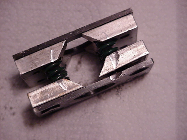 Note not only the metal loss (which must now reside somewhere) but also the fact that the severe interaction of the device has caused it to self-destruct and even loose part of itself into the gearbox. Such an approach, again, requires precise tolerances for limited movement of the pucks within the gear environment, potentially providing a slight drag on the turning of the idler gears. Another pathway to limited slip is to exert a force upon the output gears themselves, attempting to have them turn as one. Too much force results in the vehicle displaying solid axle traits. Too little results in inner tire breakaway, usually accompanied by excessive vehicle lean or lack of �squat� as some might say. In other words, too little force almost resembles a vehicle with no limited slip characteristics. To return to an explanation of the Retrofit approach versus others seen, Retrofit uses a simplified clutched design. Two halves of an assembly are fitted around the idler gear shaft. These two halves are repulsed, one from the other, toward the output gears, by specialized spring forces. Further, they are fitted with a proprietary frictional material, proprietarily bonded, that engages the differential output gear surfaces. The resultant resistance of one gear to turn without the other is accomplished. Proper adjustment insures that the resistance meets recommended levels, within a range, for best vehicular handling traits. A secondary resistance is applied when the devices two halves twist slightly and further resist the idler gears turning. Forces required to accomplish this goal must be fairly specific. Retrofit either installs the units at their assembly location or includes instructions, springs, and shims for proper installation. The springs used are Bellevilles and are noted for their linearity of force and resistance to fatigue. Of note is that the first designs of Retrofit experimented with coil springs but found that coil springs are subject to premature fatigue and failure, but more importantly, cannot provide sufficient forces necessary for desired limited slip traits. This is a very important point, with regard to others attempting to somewhat mimic their design, not to mention legal and patent issues. With the space restrictions encountered within virtually all differentials pertaining to our discussion, sufficient spring force from a coil spring simply is not available, by design or materials. Further, as the forces should be fairly precise, fairly exact spring loads are required. A few coil springs available can be preloaded sufficiently to accomplish a light amount of frictional resistance, but these springs must be overloaded to do so, and will definitely fatigue prematurely, within a very short period of time, and either break or loose their tension � a coil spring trait. Additionally, a concern with the use of coil springs, as observed within the devices marketed, is that those devices typically use the coil spring as a locator for the half pucks and are thereby subjected to torsional forces. Coil springs are not designed for torsional loads and will fail when subjected to the same. Note the locating pins of a Retrofit. 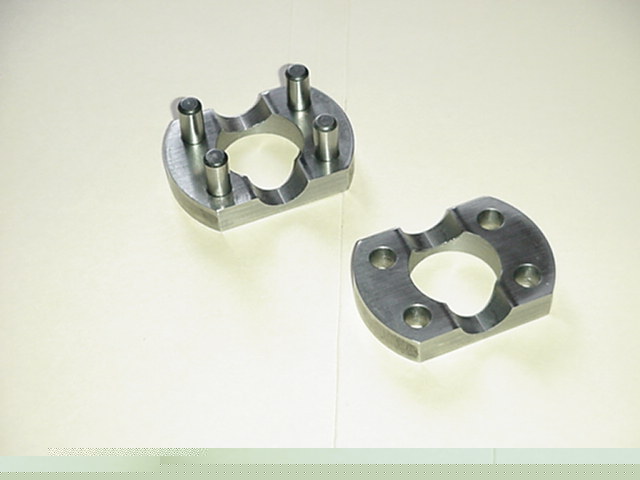 Such a design requires very precise machine work. Another extremely important consideration is the fact that metal-on-metal, in a lubricated environment (a differential) provides virtually no coefficient of friction. Some designs marketed attempt to utilize such a metal-on-metal interface between the puck halves and the output gears. Without a reasonable coefficient of friction, resistance cannot occur without incredible amounts of force, in this case, force which would distort or destroy a differential. Can coil springs provide such a force? No. If they could be large enough and strong enough to do so, again, in a metal-to-metal lubricated environment, the amount of force needed to cause a frictional engagement between the surfaces would be incredibly large � to the tune of several thousand psi. Roughly speaking, a spring similar to one on a car�s suspension would be needed. Relative to this same point, the contact area where the spring force is to be generated must be of sufficient dimension. We have observed other designs which attempt to use a very small area of the output gears. Attached is a picture of one such design. Note the severe metal decay from the attempt to do so. In using an example of such an approach, it is easy to discern the potential contact area. If the circular contact patch is from 1� in diameter to 1.2� in diameter, which is quite typical of many differential output gears, then the potential contact area for frictional interface is only .345 square inches. You may note from the picture what such an attempt can cause 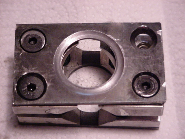 Obviously, the output gear�s surface must be machined to a constant, flat contact area, of much greater size. It is of further interest to note that in this particular design, two types of metal are used and an attempt to fasten them together with machine screws has failed. Where do you suppose the failed parts are? The following photo illustrates a prepared gear. 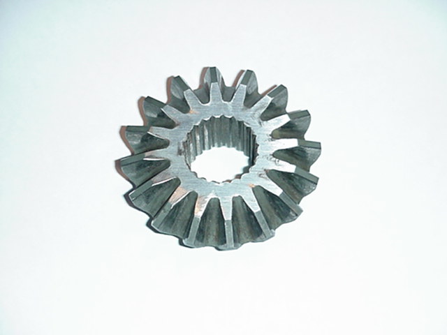 A further point addresses advertising claims seen from various manufacturers. Such claims often try to convince purchasers that a differential can detect when one tire is slipping, versus the other, from either a turn or in straight-line acceleration. This is pure fiction. Picture the function of a differential. When one tire tries to slip, it does so because it is afforded less traction than the opposing tire. This might be due to weight transfer, pavement variation, torque applied, wet conditions, or a myriad of other factors. The differential cannot �know� that such traction loss is caused by a turn or straight line. Stating that it can is outright hogwash. So what is required for limited slip to occur, correctly, in an automotive application? Some force must try to cause opposing axles to turn at the same rate, but allow slippage for proper turn negotiation. Make no mistake - it is well established that coil springs within the confines of the differential casting cannot possibly provide such a force. With respect to the designs discussed within, adequate force must also be accompanied by a sufficient coefficient of friction. Why? Because this is basically a clutch design, and, as in virtually all clutches, materials with frictional properties must be utilized to afford grip. Otherwise, incredibly large forces must be used to cause anything resembling engagement. This is especially true in a lubricated environment. Note an example of Retrofit�s frictional material 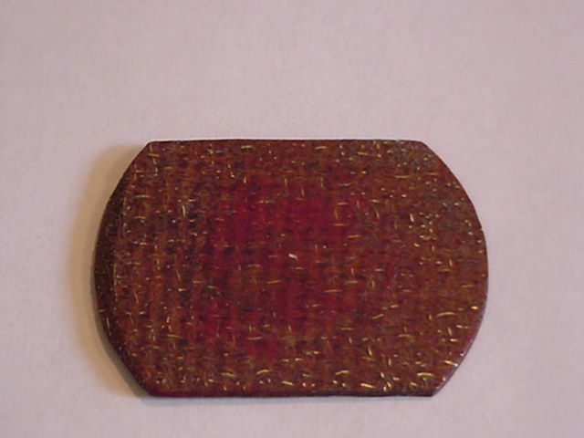 Additionally, such material must be of a composition which cannot harm gears or their environment when potential wear results. Retrofit addresses this concern in its patent and real world applications. Third, in a 2-puck design (for discussion�s sake), a need for location of the two halves, one to the other, is required. Without such a locating design, the two halves are allowed too great a range of movement, and most certainly will cause damage to the differential, and also result in excessive amounts of ground metal escaping into the housings and accompanying parts. Fourth, surface preparation of the output gears is required, if it is not already afforded, so that sufficient area is exposed for the frictional interface. Adhering to these points, and given proper design, materials, production, and preparation, such a novel approach to limited slip can be successful and quite cost effective. Carlton McCrary RetroFit Limited Slip LSD |
| Document statistics: Last modified on 2012-06-08 10:02:17 by xcasbonx |